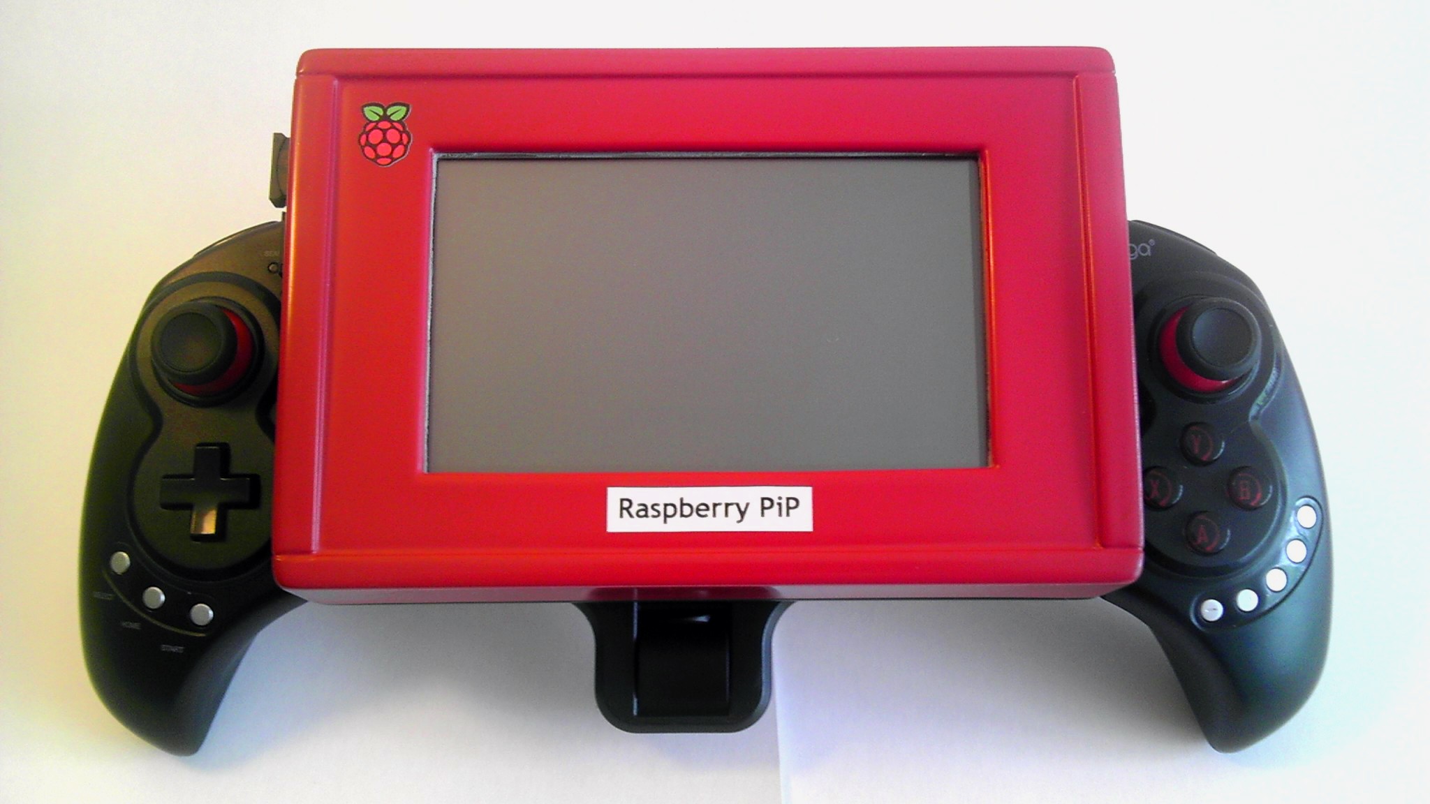
But after deciding what I really wanted to do with my chip pc, my best option was to do a landscape slate/tablet styled PiP.
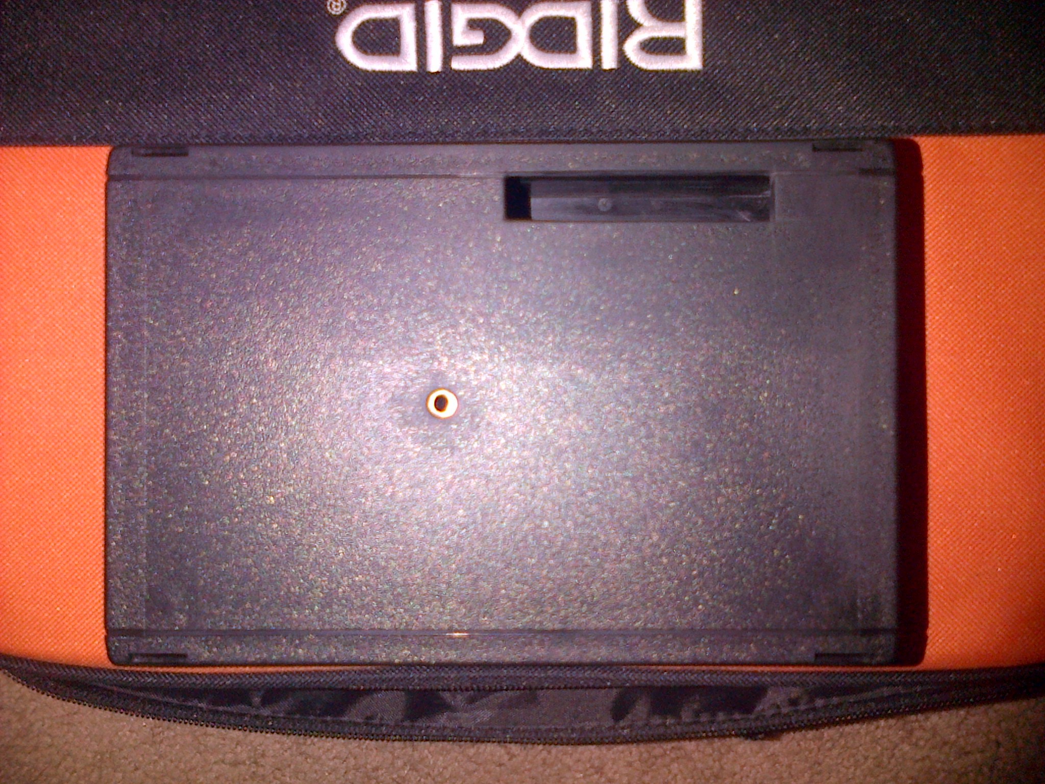
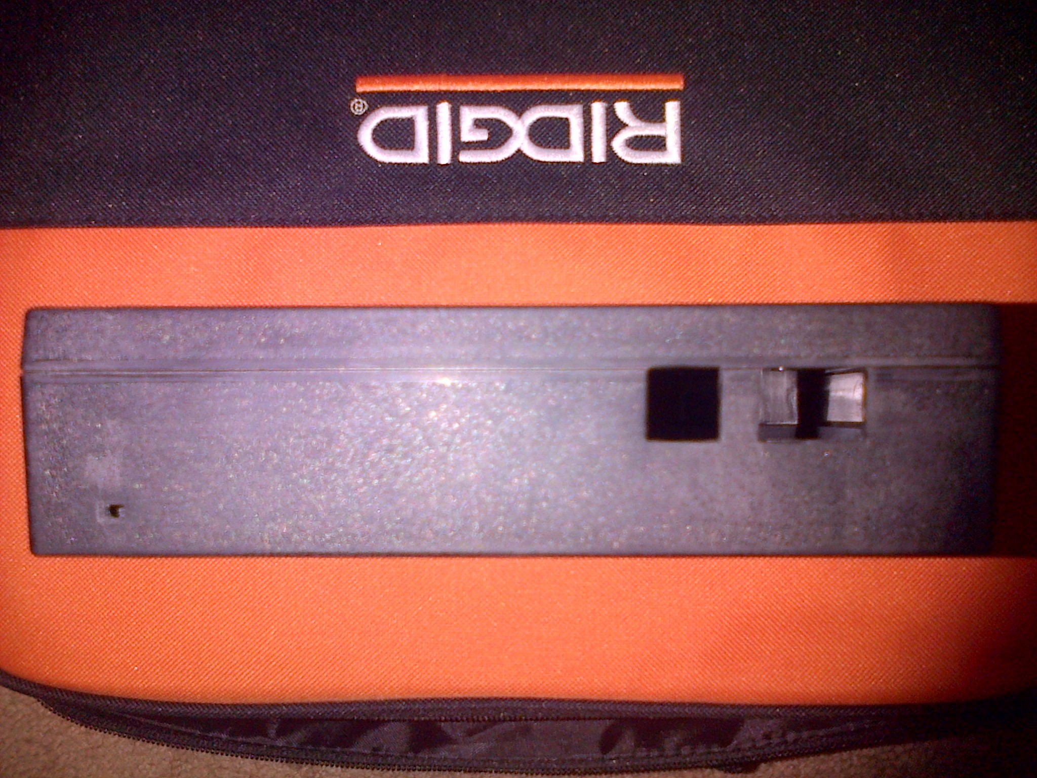
I cut the holes for the screen and inputs by hand with an x-acto knife so I could be careful to not cut away too much plastic.
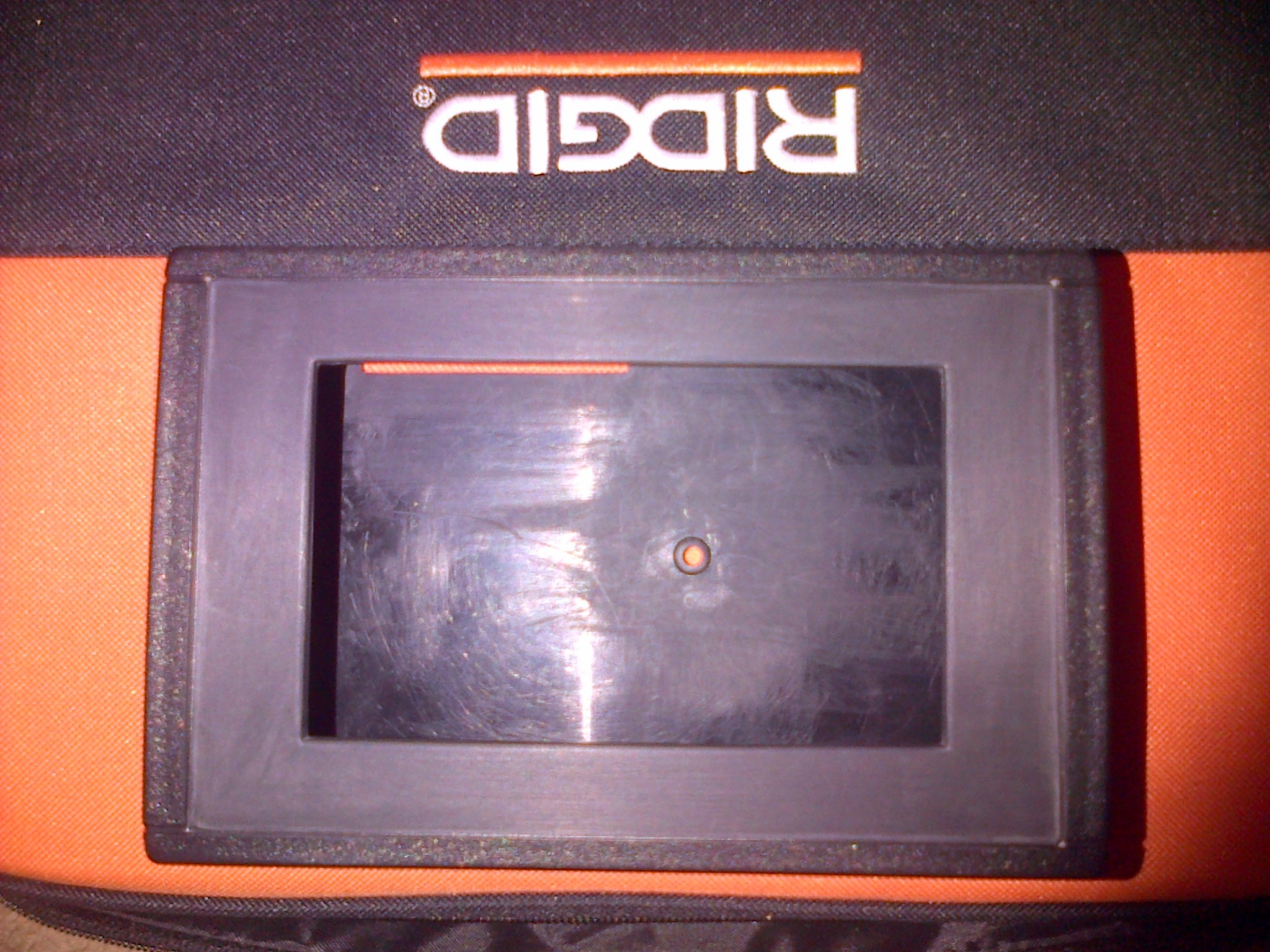
I was very tedious work... I used a small drill to do other circular holes 'n stuff. @_@
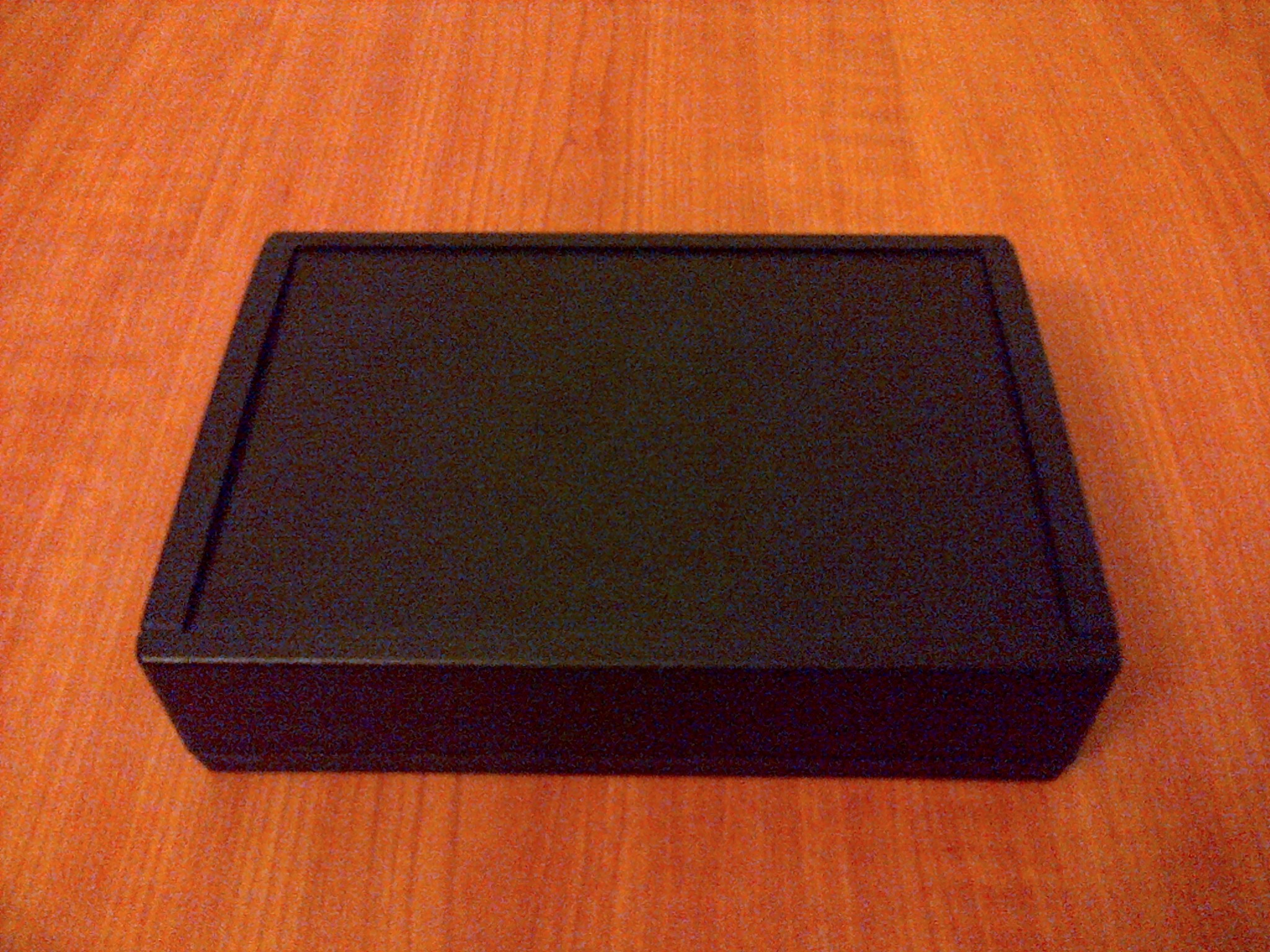
After sanding the case down and cleaning all excess dust and plastic, I used a PPS gun to spray Hi-Build Polyurethane primer over both halves.
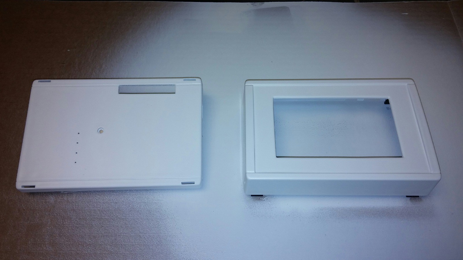
I put the case back together and sanded in between coats. The product is from the Italian coating company ILVA. Very good stuff. Powdered so nicely. We will get back to the case shortly.
Now let's talk about the actual electronic components. This will be fun. :)
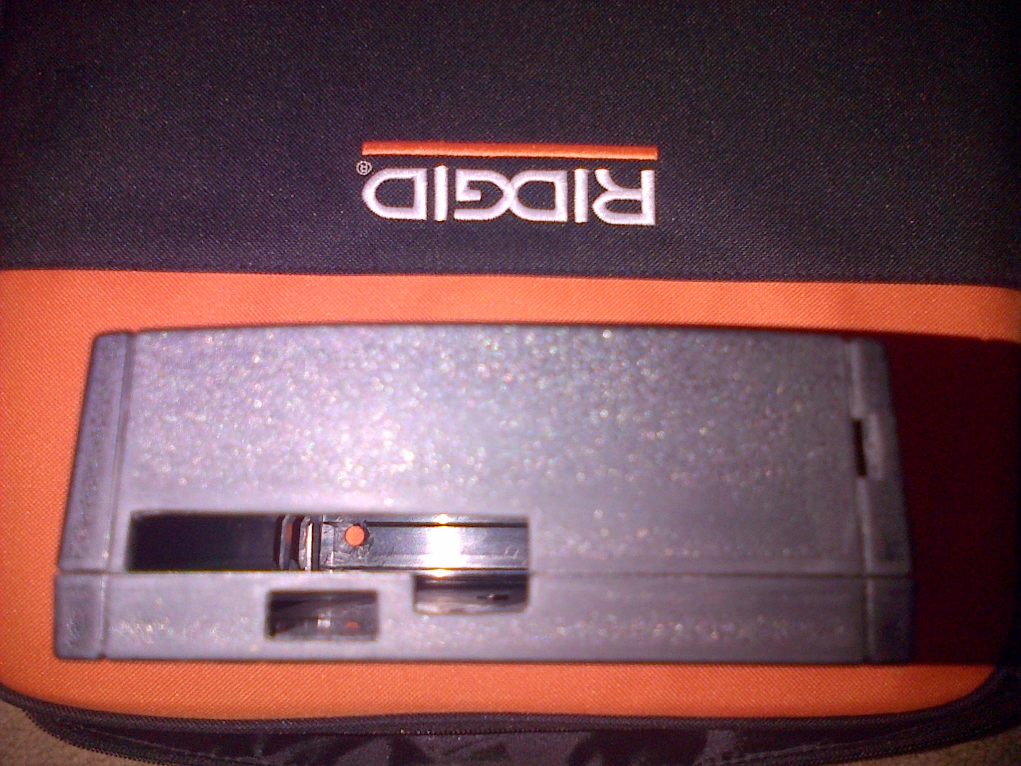
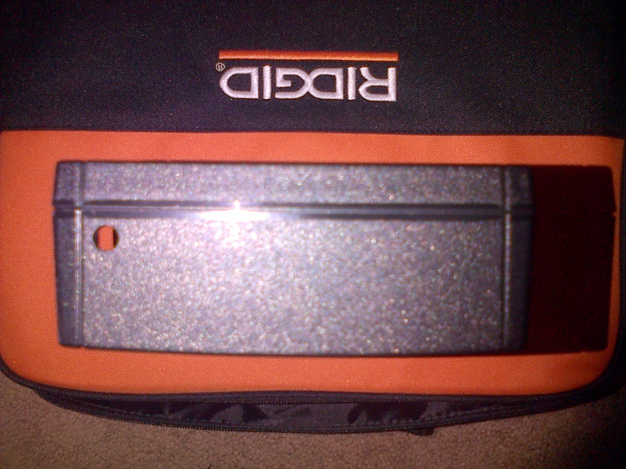
First off, power is needed to run the whole device. I bought a 8000mah usb power bank online. With both 1a and 2a outputs, It was perfect to power everything.
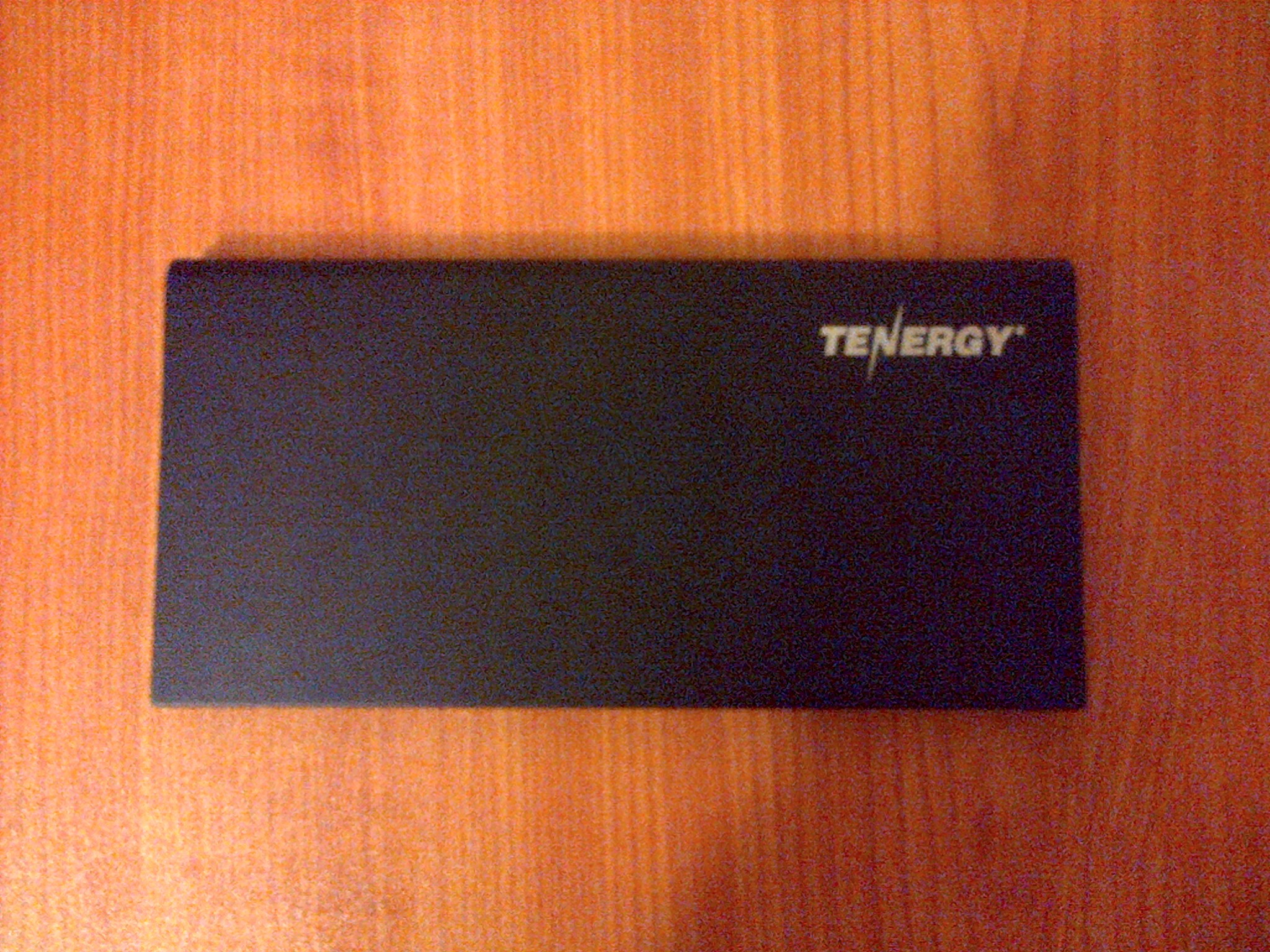
It was quite thin being only one large cell. I scored BIG TIME Ricky! IT fit perfectly in the case with room to spare.
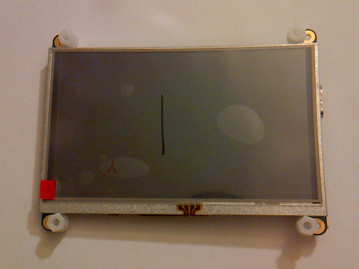
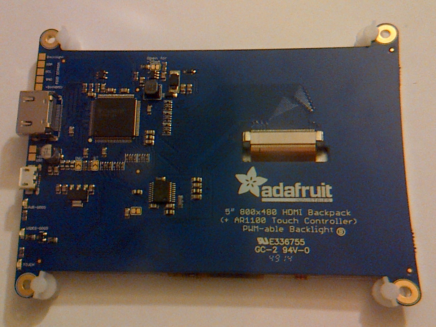
I now needed a screen and the cords to connect everything. I purchased an Adafruit 5" TFT backpack with touch, along with some usb connectors and a right angled hdmi cable.
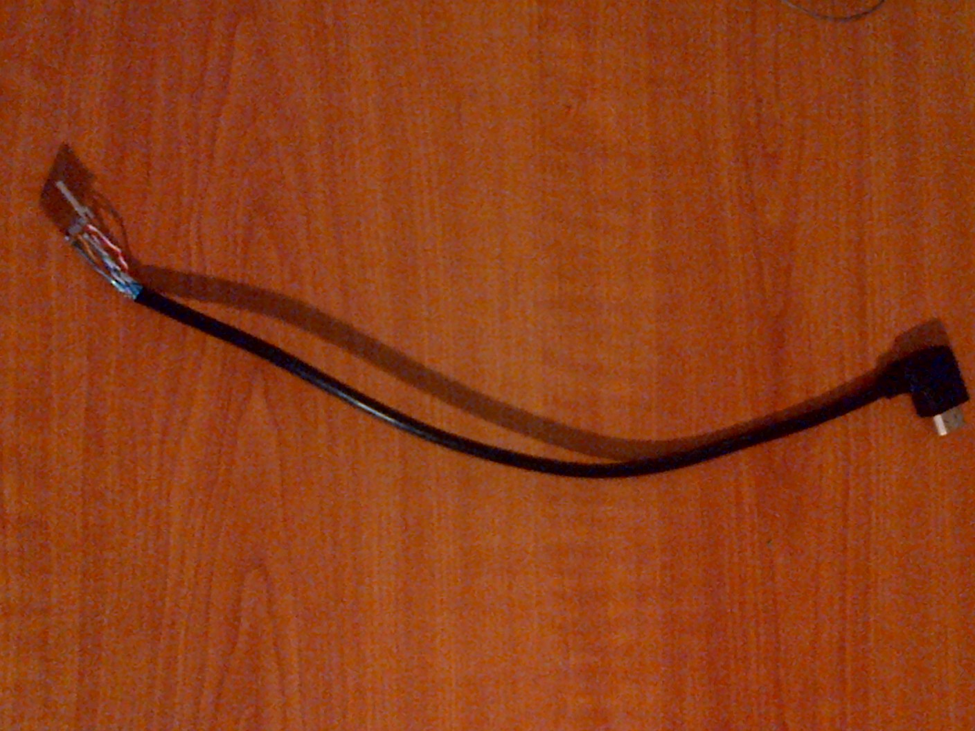
I had to cut the hdmi cable to shorten it and attach a new male end so that it would fit inside the case when plugged into the screen.
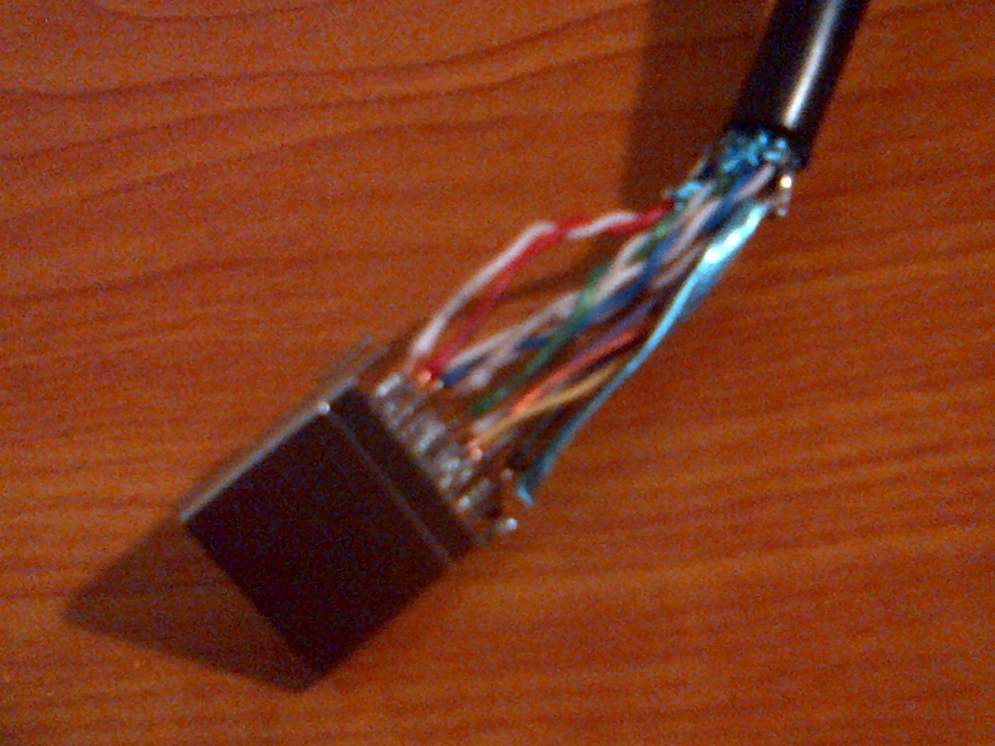
That's a lot of wires. CURSE YOU HIGH DEF VIDEO!!!!!!!!!!!!!!!!!!!!!!!!! worth it tho.
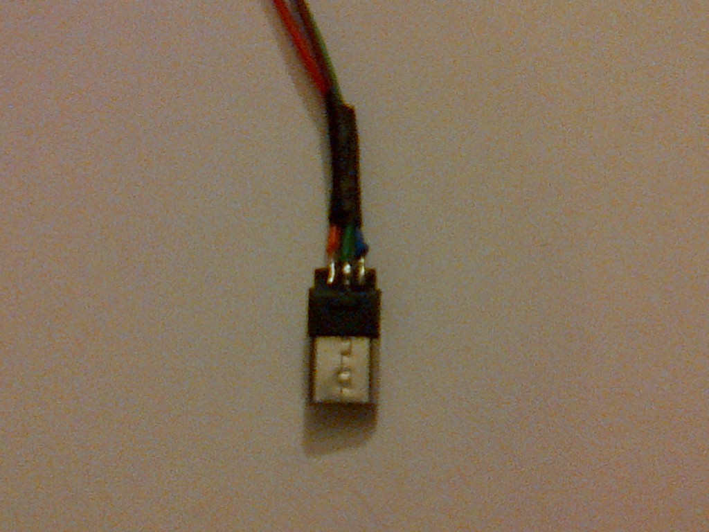
I made a few micro usb cables to connect to the Pi and the screen.
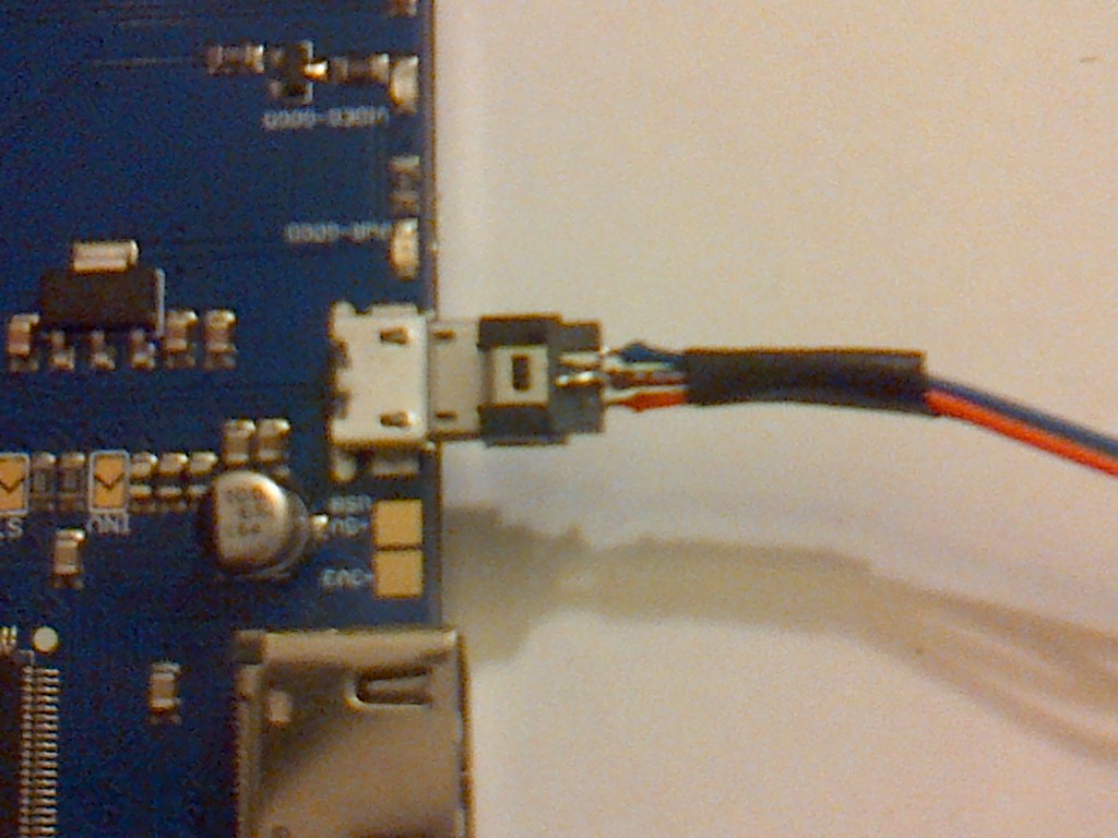
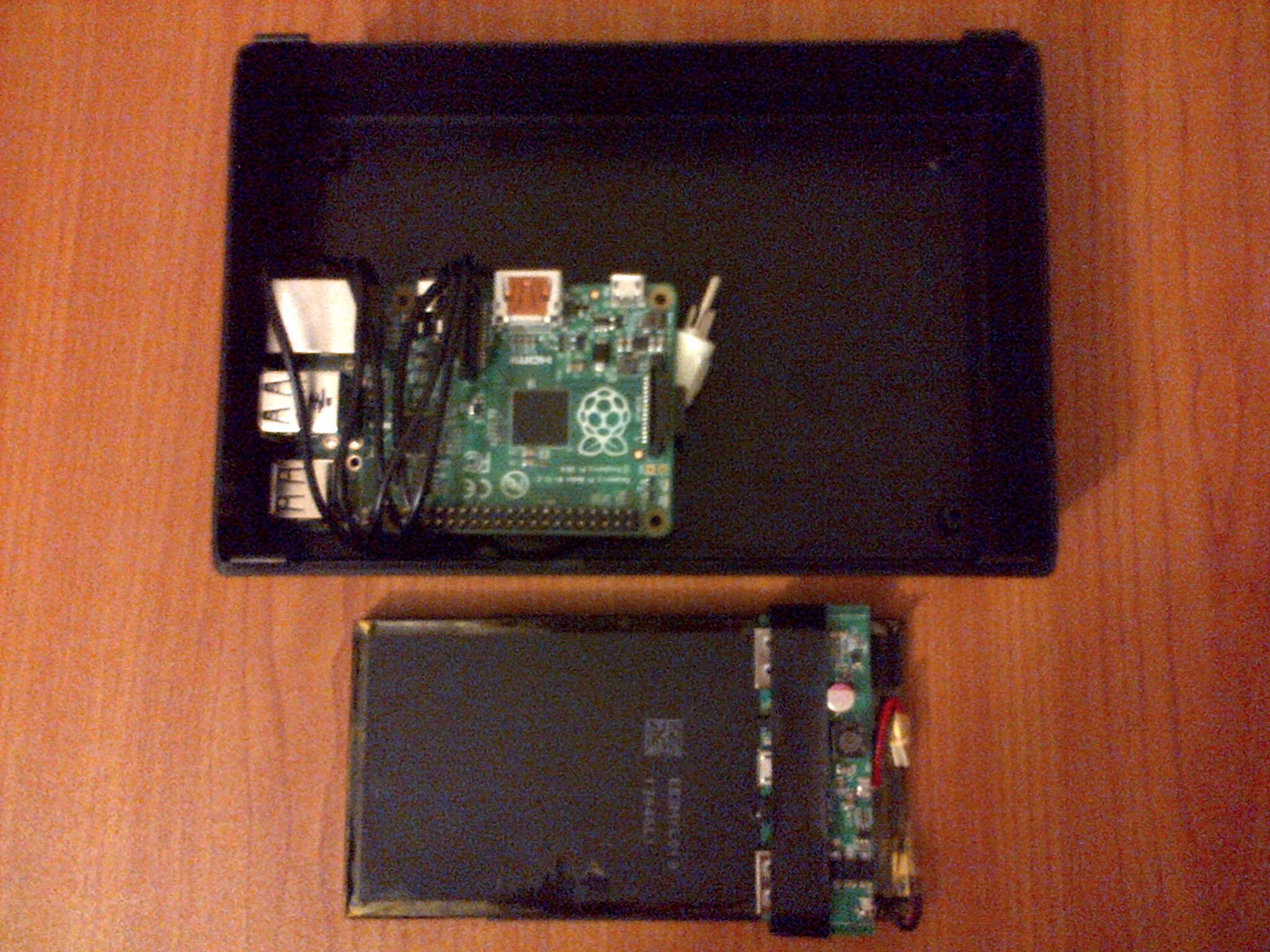
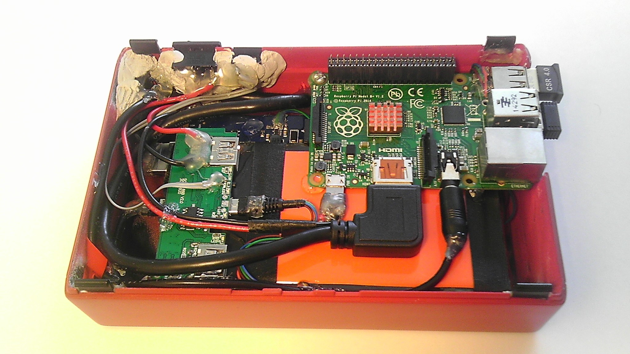
Already having a RPi B+, I removed one of the dual usb ports from the board and attached a new single usb port.
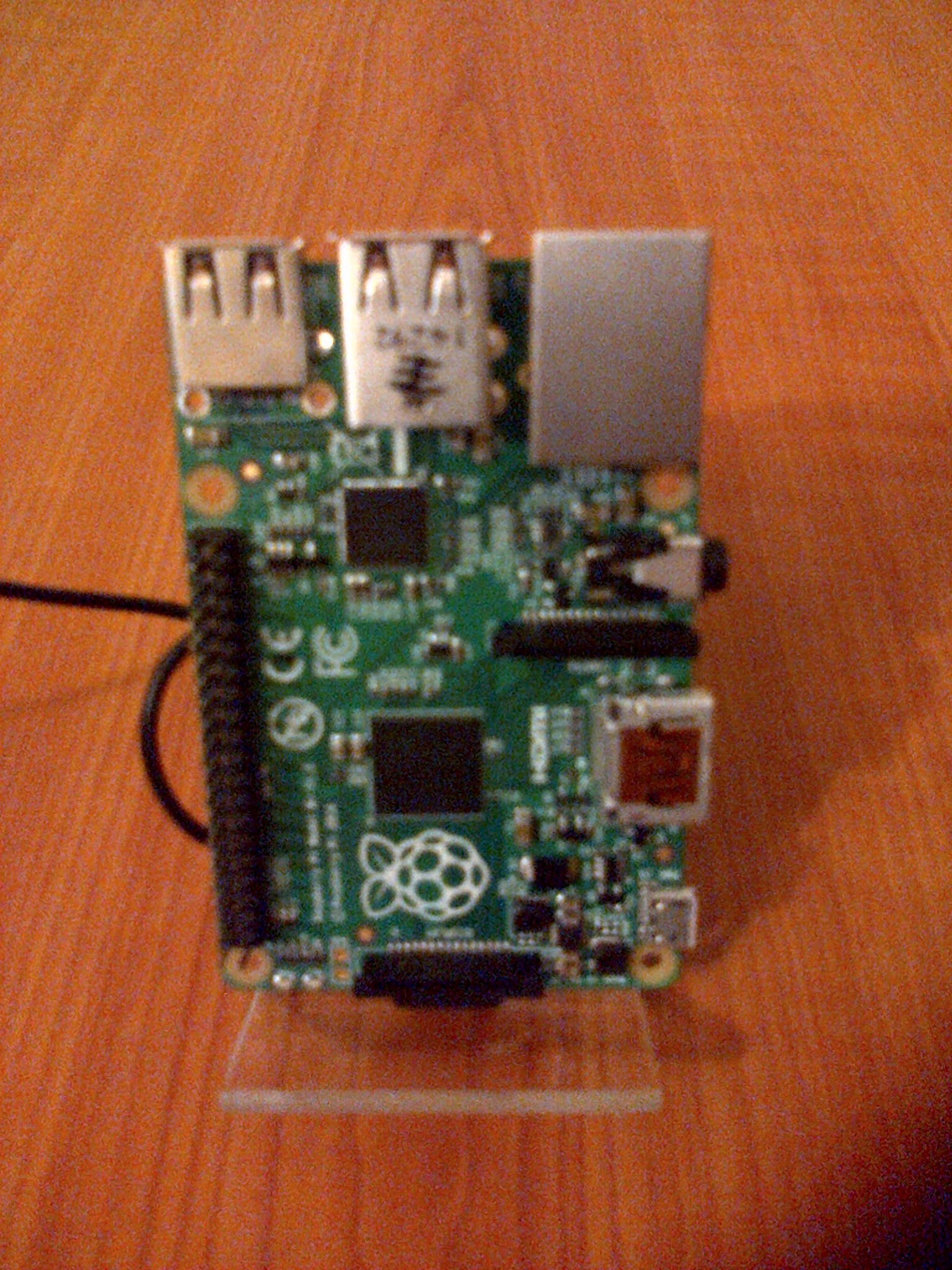
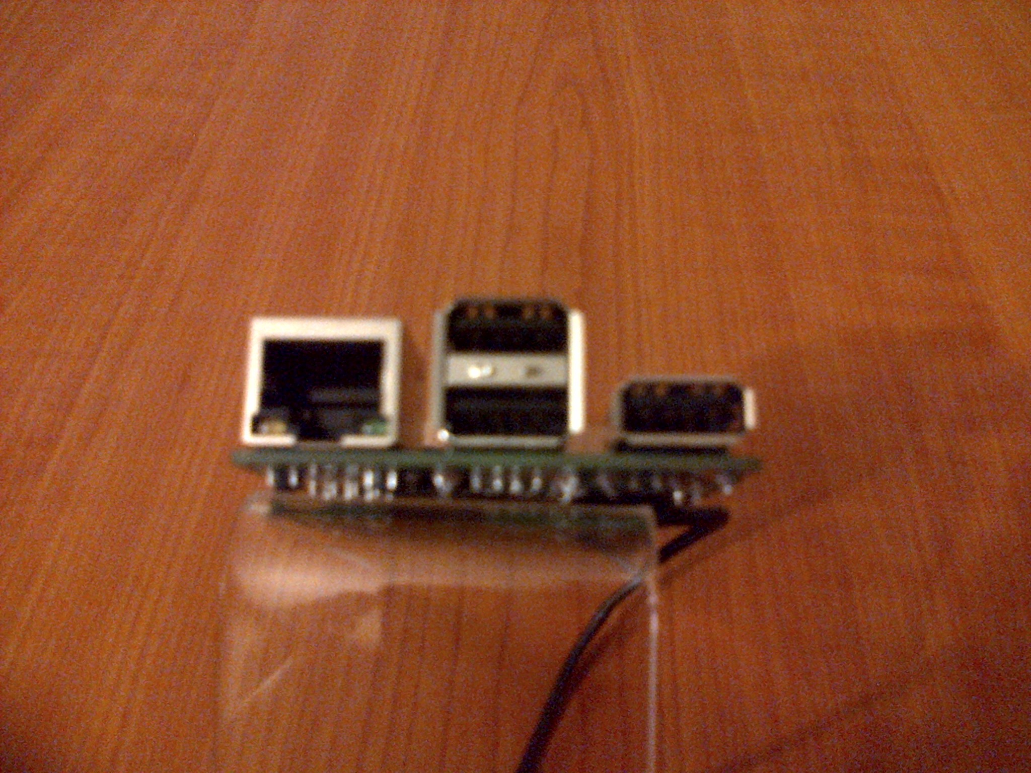
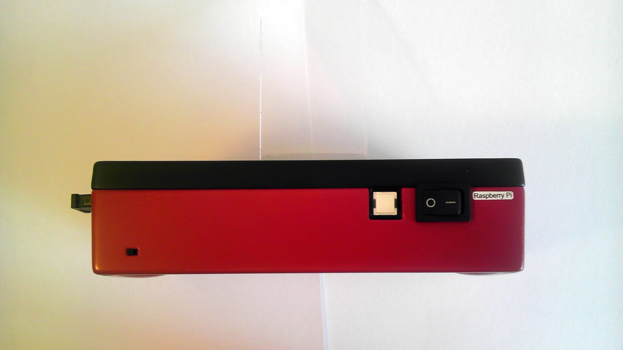
Then I soldered a micro usb plug to the open pins on the Pi to power the screen. Next was to solder the power switch circuit and the 3.5mm audio jack for sound.
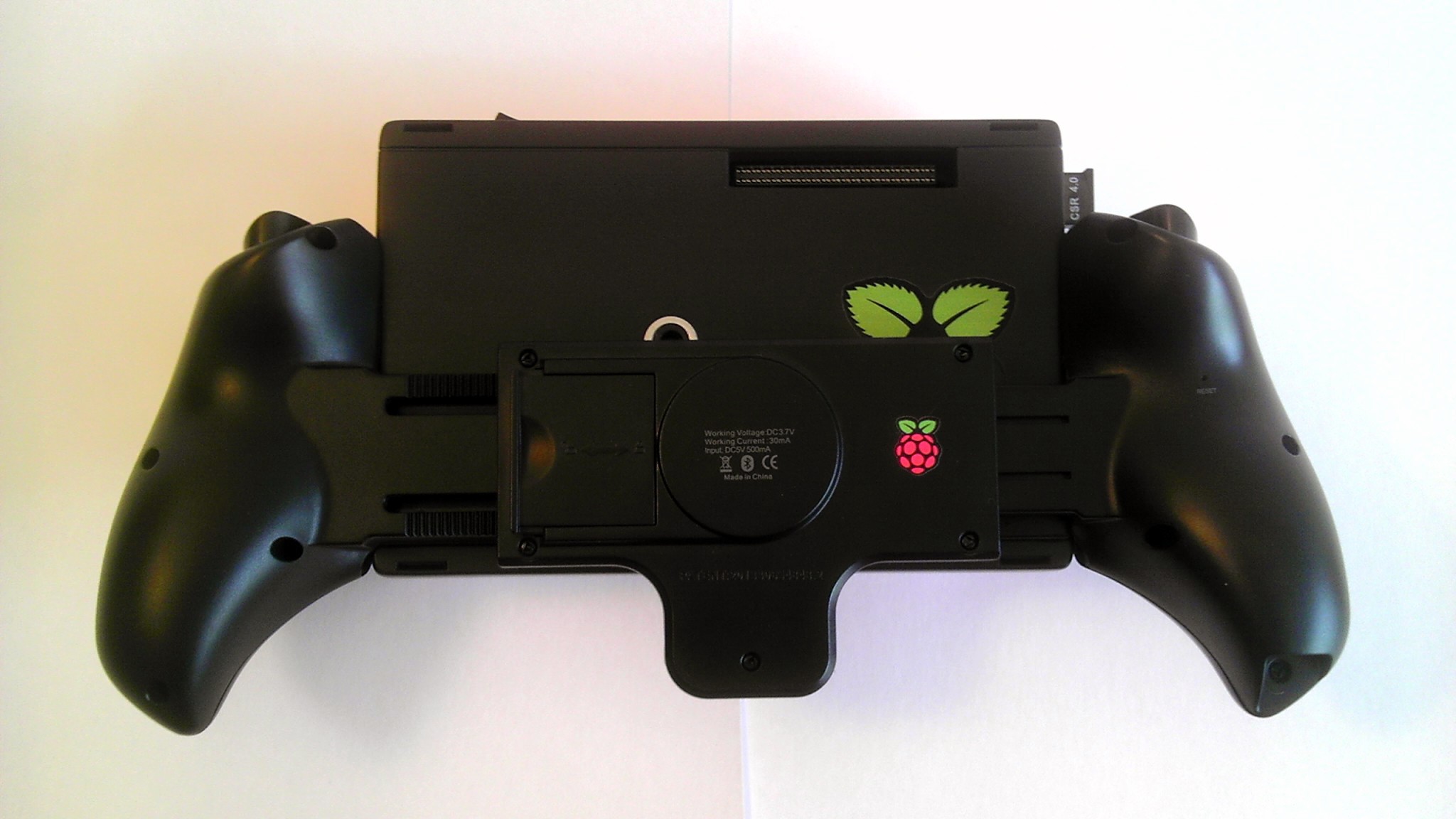
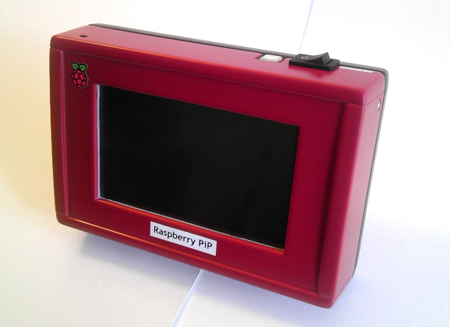
Finally I could fit everything together inside the case. But not before finishing the topcoat polyurethane coating. Raspberry Red on the front, matte slate gray on the back.
I had to loop some wires inside the case and glue down the ports to the inner walls. It may be a bit messy, but it is sturdy and leaves room for air flow.
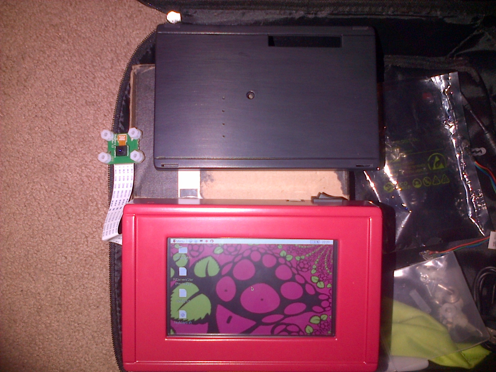
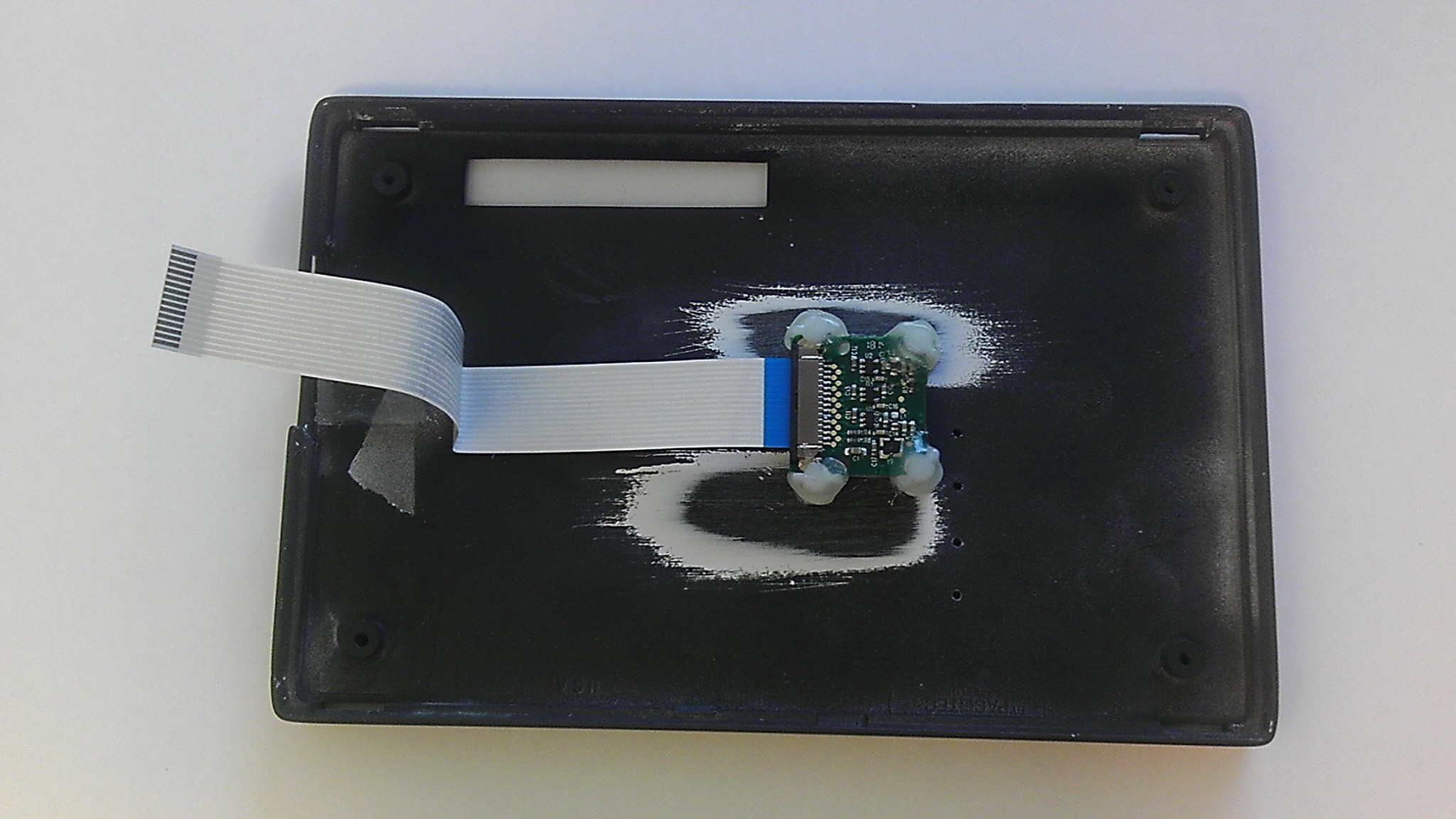
I attached the Picam to the back of the case with circuit board mounts and glue.
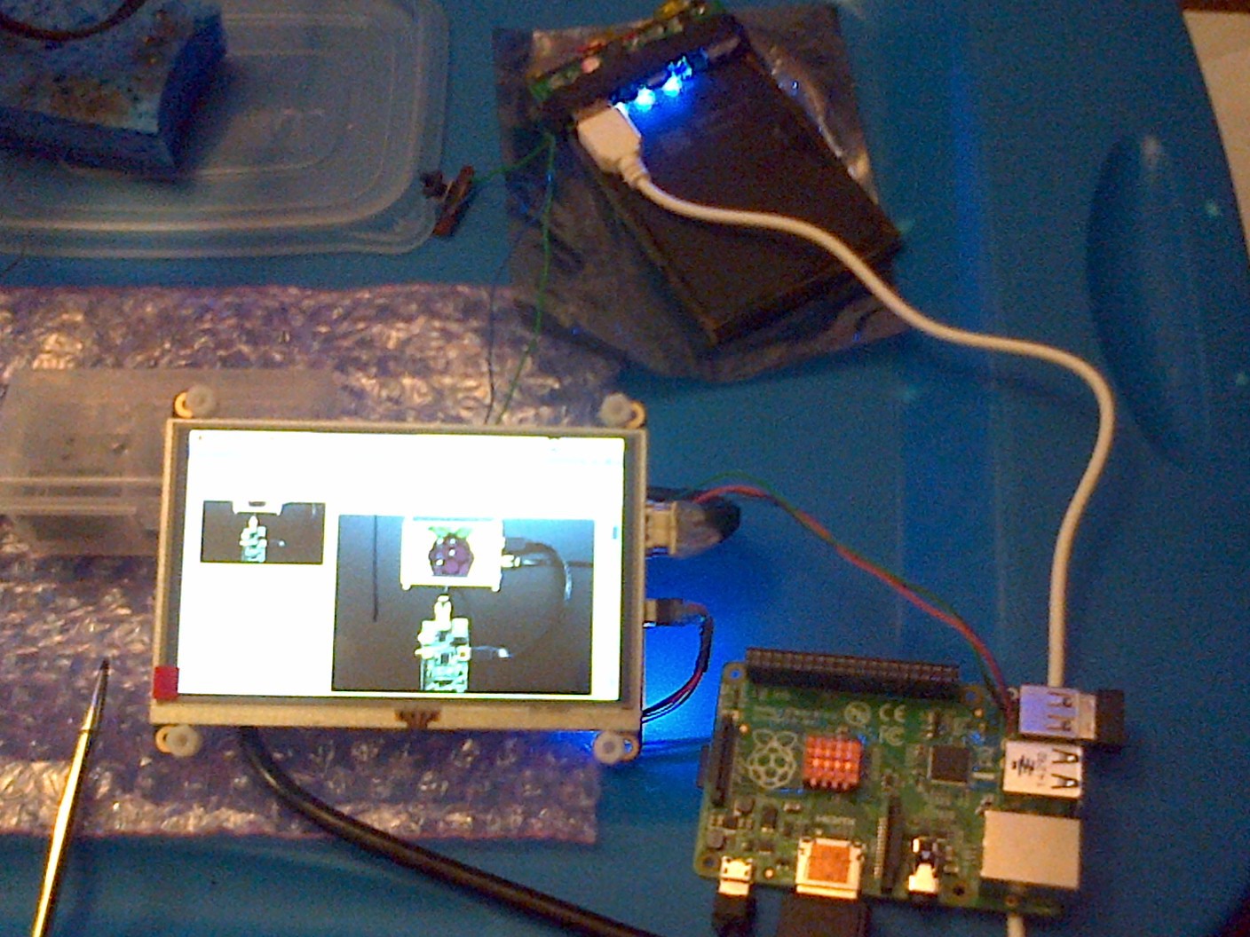
Finally my creation is ready to come alive!
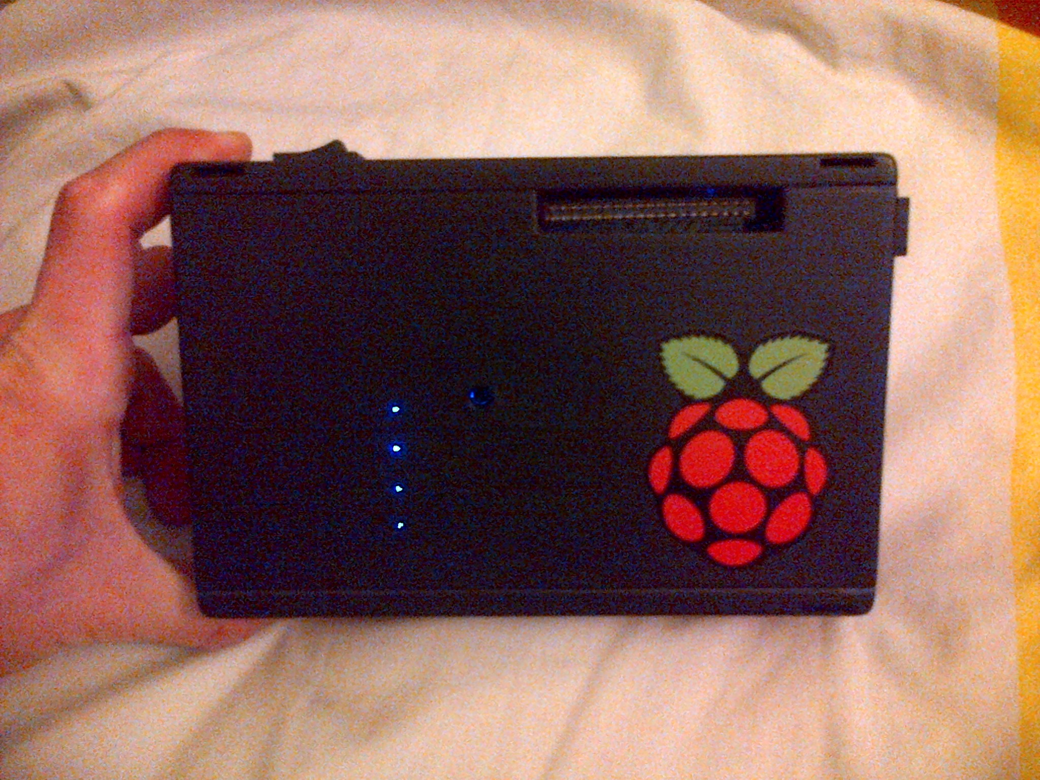
IT WORKS!!!! YIS!
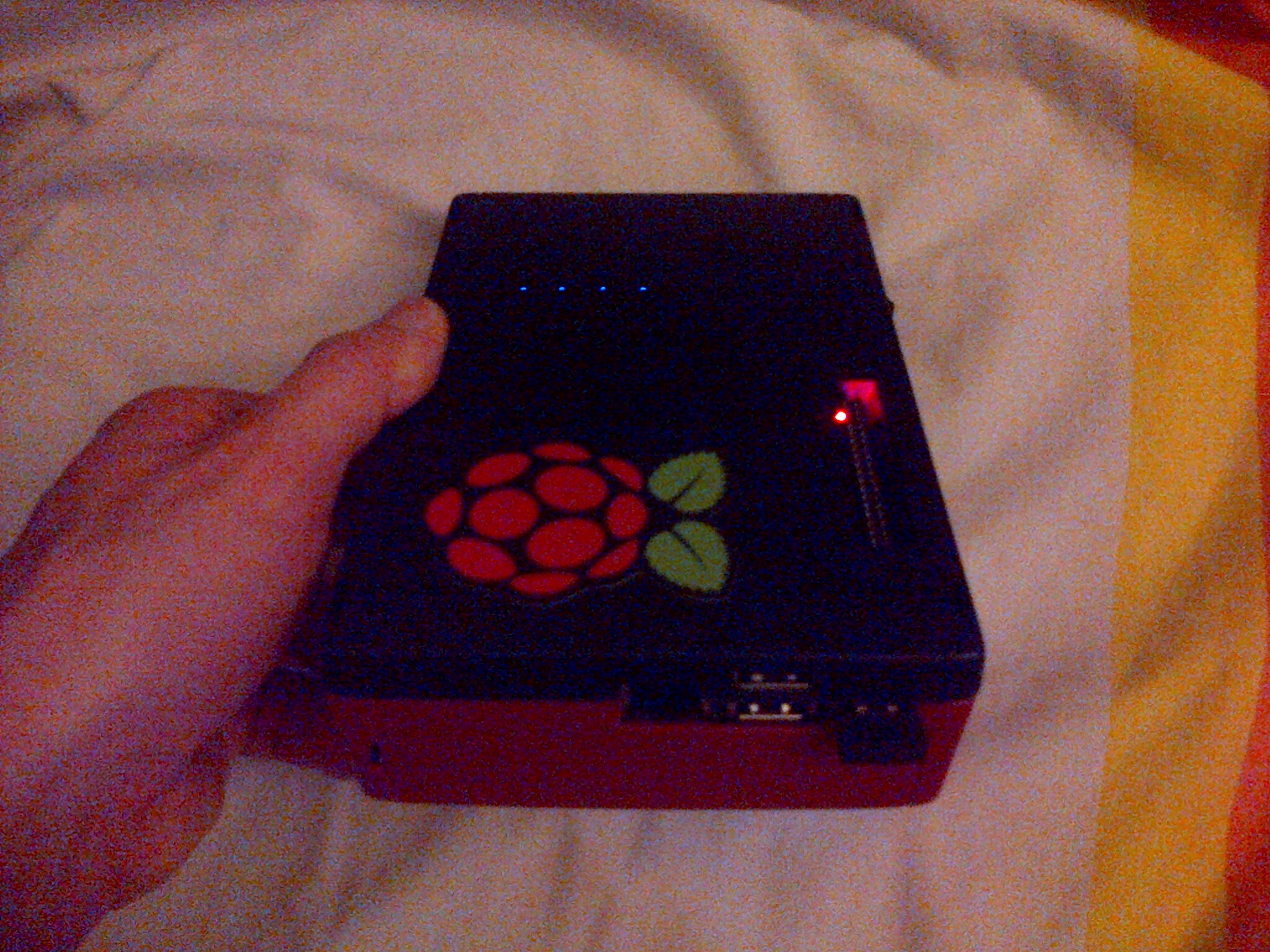
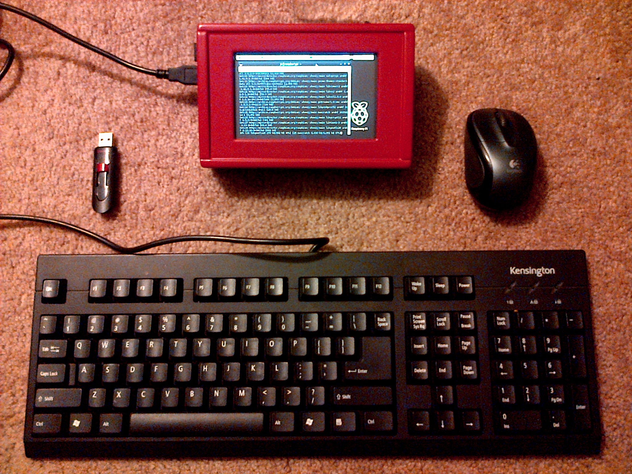
Check out my new workstation below. lolz.
So that's how I did it, lots of blood, sweat, and bizarre raspberry dreams to be had.
Here's some more shots...
I WOULD LIKE TO GIVE A BIG SPECIAL THANKS TO MY LOVELY GIRLFRIEND FOR BEING MY SUPPORT THROUGH THIS PROJECT, AND FOR HELPING ME ALONG THE WAY!
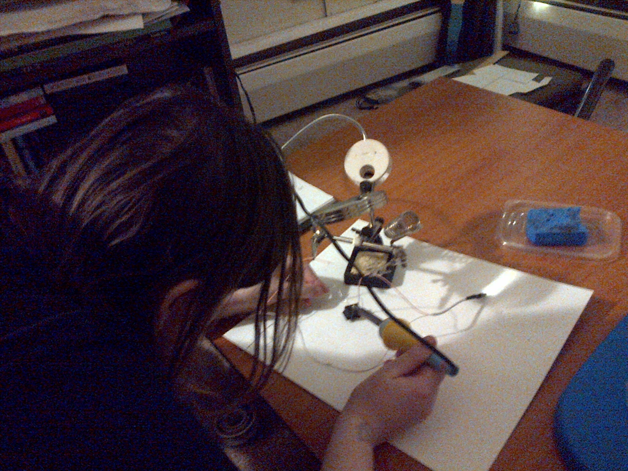
Natural solder wiz right there. Tell me how many girlfriends would do that? Hehe. ;)
Thanks for checking out my project page. I'm sure I will add updates in my project logs down the line. Don't forget to skull and follow! Be mindful! <3